
When the Oil Film Is No Longer Sufficient: A New Criterion for the Operating Regime of a Sliding Pair
A practical adaptation of research on lubricant-film behavior in sliding pairs (SP), accounting for the non-Newtonian behavior of lubricants. For marine engineers, technical superintendents, inspectors, and condition-monitoring specialists.
Summary. Monitoring is based on a simple check: the calculated influence coefficient for lubricant properties and operating conditions  must be less than the criterion
 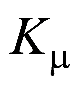 . If
. If  , the mathematical model yields a physically correct, bounded distribution of hydrodynamic pressure in the oil film; in other words, the condition for full-film lubrication in the sliding pair is satisfied. The main value of the approach is that it combines bearing geometry, rotational speed, and lubricant properties in a single test. The approach is based on the author's studies [1-4].
1. What exactly is proposed for monitoring?
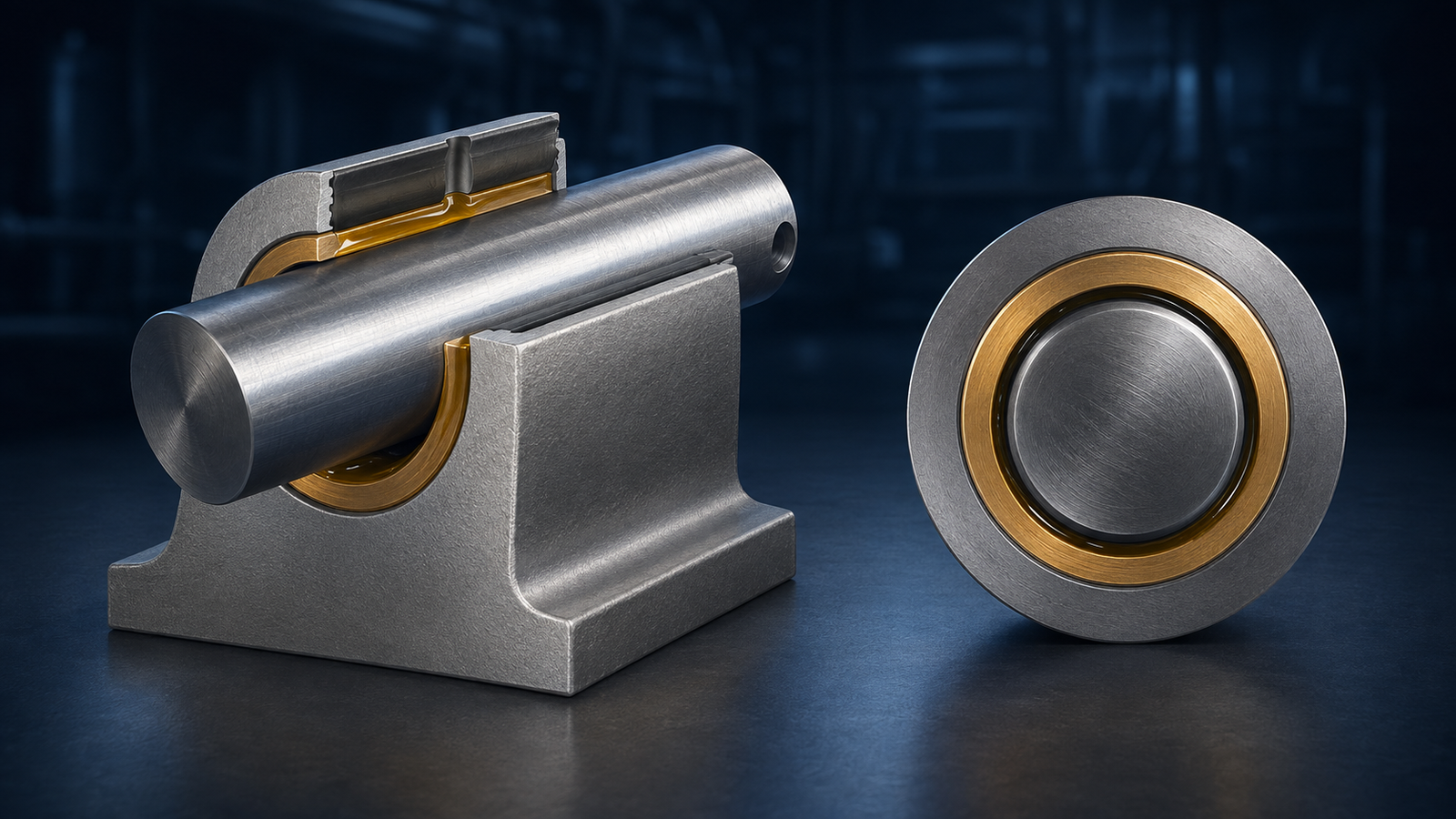
A conventional sliding pair operates not simply because the surfaces are 'well lubricated' in the everyday sense, but because rotation of the journal creates a stable oil wedge between the shaft and the bearing shell. Hydrodynamic pressure develops in this wedge, carries the load, and prevents direct contact between the surfaces. This is especially important in marine diesel engines: main and connecting-rod bearings operate under high, variable loads; similar sliding pairs are also found in shaft-support bearings and other components of the propulsion system. In this study, the task is formulated specifically as monitoring the preservation of the full-film lubrication regime, i.e., the presence of a complete oil film between the bearing shell and the journal, taking into account the technical parameters of the sliding pair and the properties of the lubricant.
Key engineering idea: The criterion is intended to answer a practical question: are the bearing parameters and lubricant properties compatible with the mathematical condition for a stable full-film lubrication regime?
2. Why nominal lubricant viscosity alone is not enough
In routine practice, viscosity is often treated as a lubricant property at a specified temperature. However, inside a loaded bearing, pressure in the oil wedge varies and can reach significant values. This, in turn, can substantially change the lubricant's dynamic viscosity; thus, lubricant behavior in the working zone of the sliding pair is non-Newtonian. The dependence of dynamic viscosity 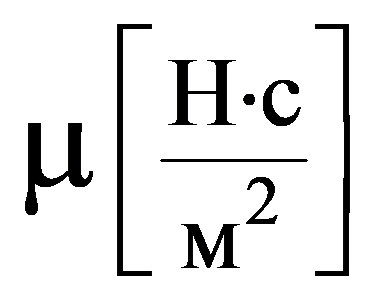 on hydrodynamic pressure
 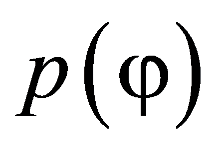 in the oil film is proposed to be described by the Barus equation:
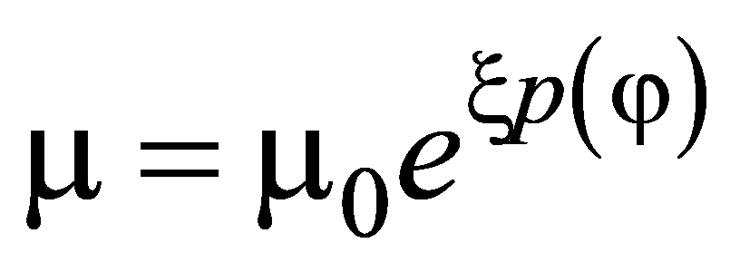
where 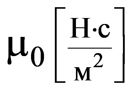 is the dynamic viscosity at atmospheric pressure;
  is the pressure-viscosity coefficient (piezoviscosity coefficient) of the lubricant.
The pressure-viscosity coefficient  indicates how strongly viscosity responds to pressure. As ξ tends to zero, the pressure dependence disappears and the model reduces to the Newtonian case. For practical calculations, the viscosity gradient is also important, i.e., how rapidly
  changes with :
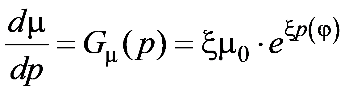
At atmospheric pressure,  .
.
These parameters depend on temperature and should be determined experimentally or taken from reliable data for the specific lubricant. Table 2 provides values of  and
and  at 60°C, 80°C, and 90°C for lubricants used with ten representative types of marine engines.
3. The second key parameter - displacement of the journal center within the bearing.
In real journal bearings, the center of the journal does not coincide with the center of the bearing shell. Under load, the shaft is displaced, so the clearance decreases on one side and increases on the other. This displacement is described by the relative eccentricity (eccentricity ratio):  , where ε is the eccentricity between the centers of the sliding-pair members;
  the radial clearance.
The closer  is to unity, the farther the shaft is displaced toward the bearing-shell surface and the smaller the oil-film thickness at the minimum clearance. The studies showed that increases as the load increases and rotational speed decreases. For connecting-rod bearings, under the operating conditions considered, is slightly higher than for main bearings. During operation, the relative eccentricity can be determined using vibrometers, bearing-condition indicators, bearing-condition analyzers, and other diagnostic equipment. The specific procedure depends on the installed monitoring system and the engine calculation model.
4. Criterion for the full-film lubrication regime.
Accounting for the non-Newtonian behavior of lubricants in the differential Reynolds equation for the lubricant film in a sliding pair made it possible to obtain the following two dimensionless quantities [1-4]:
- Influence coefficient
 :
:
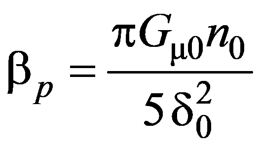 ,
,
where  the rotational frequency of the journal;
  the relative radial clearance of the plain bearing.
For an operating engineer, it is convenient to interpret as the 'current level of influence' of lubricant rheology and the rotational regime on the oil film in the sliding pair. It is neither a measured pressure nor a percentage of load; it is a dimensionless model parameter.
- Criterion number
 , for which studies [1-3] obtained an approximate expression in terms of the relative eccentricity :

Criterion depends on the relative eccentricity . Specifically, as the shaft moves toward the bearing shell (as increases), the permissible region defined by the criterion rapidly narrows. This is clearly shown in Figure 1.
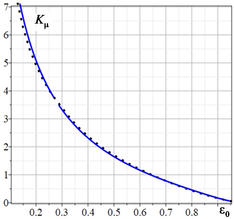
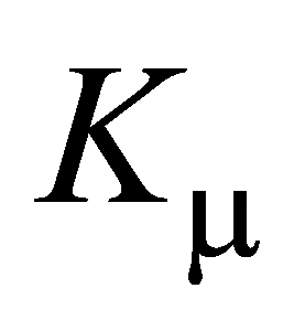 on .
on .Using the quantities obtained above, the criterion for the full-film lubrication regime is associated with satisfying the condition

If the inequality is satisfied, the calculated specific hydrodynamic pressure in the working zone remains non-negative and bounded. As approaches , the margin with respect to this criterion decreases. If becomes greater than , the model no longer satisfies the condition on which the full-film lubrication description is based. This is grounds for closer monitoring of the sliding pair, taking into account temperature, vibration, actual clearance, and detailed oil analysis.
5. What validation of the proposed criterion showed for the main types of marine engines
To validate the proposed criterion, the operation of the main types of marine engines D1-D10 listed in Table 1 was studied under steady-state conditions ([1, 2]). The table also provides several design and calculation parameters for the main and connecting-rod sliding pairs (SPs) of these engines, including:
- mean specific load of the main bearings
 ;
; - mean specific load of the connecting-rod bearings
 ;
; - maximum possible rotational speed
 ;
; - rated operating speed n0 [rpm];
- relative radial clearance of the main bearings
 ;
; - relative radial clearance of the connecting-rod bearings
 .
.
Table 1. Operating parameters of the main and connecting-rod sliding pairs.
| D | Engine |  |
 |
 |
 |
 |
 |
|---|---|---|---|---|---|---|---|
| 1 | Sulzer 9RTA84C | 8÷ 12 | 10÷14 | 102 | 90 ÷ 100 | 0.714÷ .952 | 1.00÷ 1.28 |
| 2 | Sulzer 7RTA68 | 8÷ 12 | 10÷ 14 | 102 | 90÷100 | 0.882÷ 1.176 | 1.25÷ 1.61 |
| 3 | MAN B&W 6S50ME | 6÷ 10 | 8÷12 | 127 | 120 | 0.962÷1.35 | 1.25÷2.00 |
| 4 | MAN 12V48/60CR | 5÷8 | 7÷10 | 514 | 500 | 0.83÷1.25 | 1.32÷1.84 |
| 5 | Wärtsilä 46F | 7÷ 10 | 9÷13 | 600 | 540÷600 | 1.087÷1.52 | 1.58÷2.11 |
| 6 | Wärtsilä 9L32 | 4÷7 | 6÷9 | 750 | 720 | 1.25÷1.875 | 1.92÷2.69 |
| 7 | MAN 8L27/38 | 4÷6 | 5÷8 | 800 | 720÷750 | 1.481÷2.22 | 2.27÷3.18 |
| 8 | Yanmar 6EY22 | 5÷7 | 6÷9 | 1000 | 720÷900 | 1.364÷2.273 | 2.22÷3.33 |
| 9 | MTU 20V4000 | 6÷9 | 8÷12 | 1900 | 1800 | 1.50÷2.50 | 2.22÷3.33 |
| 10 | MTU 16V4000 M93 | 6÷9 | 8÷12 | 1900 | 1800 | 1.50÷2.50 | 2.22÷3.33 |
Table 2 lists the recommended lubricants for engines D1-D10, together with their dynamic viscosity  and pressure-viscosity coefficient
  at the principal temperatures in the lubrication operating cycle: 60°C, 80°C, and 90°C.
Table 2. Lubricants, their dynamic viscosity, and pressure-viscosity coefficient at different temperatures for engines D1-D10.
 |
 |
||||||
|---|---|---|---|---|---|---|---|
| D | Lubricant | 60° | 80° | 90° | 60° | 80° | 90° |
| 1 | TotalAtlantaMarineD3005 | 42.08 | 26.93 | 21.54 | 3.3 | 3 | 2.8 |
| 2 | BP Vanellus Multi | 48.51 | 31.04 | 24.83 | 2.9 | 2.6 | 2.4 |
| 3 | Mobilgard™ 300 | 41.56 | 26.6 | 21.28 | 2.9 | 2.6 | 2.4 |
| 4 | Shell Argina T | 44.62 | 28.56 | 22.85 | 3.4 | 3.1 | 2.9 |
| 5 | Chevron Delo 400 MGX | 46.98 | 30.07 | 24.05 | 3.9 | 3.6 | 3.4 |
| 6 | Castrol CDX 30 | 41.82 | 26.76 | 21.41 | 2.4 | 2.1 | 1.9 |
| 7 | Shell RimulaR4X15W-40 | 47.08 | 30.13 | 24.10 | 3.9 | 3.6 | 3.4 |
| 8 | Yanmar Genuine Oil 15W-40 | 43.68 | 27.96 | 22.36 | 3.4 | 3.1 | 2.9 |
| 9 | ExxonMobilDelvac1LE5W-30 | 36.57 | 23.41 | 18.73 | 2.4 | 2.1 | 1.9 |
| 10 | Mobil Delvac MX 15W-40 | 49.5 | 31.68 | 25.34 | 2.4 | 2.1 | 1.9 |
The data in Tables 1 and 2 make it possible to calculate the relative eccentricity  , criterion
 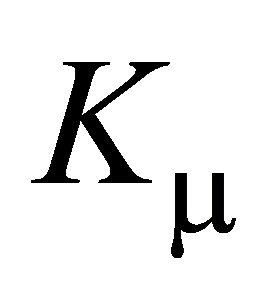 , and influence coefficient . The corresponding values for the main and connecting-rod sliding pairs of engines D1-D10 are given in Tables 3 and 4, respectively.
Table 3. Verification of criterion 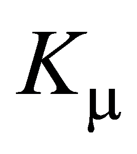 for main sliding pairs
| D | |
|
 |
||
|---|---|---|---|---|---|
| 60° | 80° | 90° | |||
| 1 | 0.82 | 0.398 | 0.171 | 0.099 | 0.074 |
| 2 | 0.80 | 0.459 | 0.114 | 0.065 | 0.048 |
| 3 | 0.75 | 0.616 | 0.098 | 0.056 | 0.042 |
| 4 | 0.65 | 0.964 | 0.686 | 0.401 | 0.300 |
| 5 | 0.65 | 0.964 | 0.585 | 0.345 | 0.261 |
| 6 | 0.59 | 1.342 | 0.291 | 0.163 | 0.118 |
| 7 | 0.55 | 1.390 | 0.394 | 0.233 | 0.176 |
| 8 | 0.45 | 1.953 | 0.452 | 0.264 | 0.197 |
| 9 | 0.43 | 2.090 | 0.441 | 0.247 | 0.179 |
| 10 | 0.43 | 2.090 | 0.597 | 0.334 | 0.242 |
Table 4. Criterion values for connecting-rod sliding pairs
| D |  |
 |
 |
||
|---|---|---|---|---|---|
| 60°С | 80°С | 90°С | |||
| 1 | 0.83 | 0.368 | 0.087 | 0.051 | 0.038 |
| 2 | 0.80 | 0.459 | 0.057 | 0.032 | 0.024 |
| 3 | 0.72 | 0.715 | 0.058 | 0.033 | 0.025 |
| 4 | 0.65 | 0.964 | 0.275 | 0.161 | 0.120 |
| 5 | 0.70 | 0.783 | 0.277 | 0.164 | 0.124 |
| 6 | 0.59 | 1.207 | 0.123 | 0.069 | 0.050 |
| 7 | 0.57 | 1.296 | 0.168 | 0.099 | 0.075 |
| 8 | 0.50 | 1.649 | 0.170 | 0.099 | 0.074 |
| 9 | 0.47 | 1.825 | 0.201 | 0.113 | 0.082 |
| 10 | 0.45 | 1.953 | 0.272 | 0.152 | 0.110 |
Note that Tables 3 and 4 present the maximum possible values of relative eccentricity  for each engine type under steady-state operating conditions. Values of can also be determined online during engine operation using vibrometers, bearing-condition indicators, bearing-condition analyzers, and other equipment. The other parameters were calculated using data from Table 2.
6. Conclusions and recommendations for applying the results.
Solving the boundary-value problem for the Reynolds equation while accounting for the non-Newtonian behavior of lubricants, together with the numerical modeling, led to the following conclusions that are important for practical application:
- As the load on the sliding pair increases and the journal rotational speed decreases, the relative eccentricity
 increases. For connecting-rod sliding pairs, is somewhat higher than for main sliding pairs.
 - Criterion is satisfied under steady-state operating conditions for both main and connecting-rod sliding pairs at the principal temperatures in the lubrication cycle - 60°C, 80°C, and 90°C - for the main marine-engine types D1-D10.
- For the new lubricants listed in Table 3, the criterion is satisfied at operating temperatures, and engine start-up does not produce a critical increase in hydrodynamic pressure; therefore, the sliding pair operates in the full-film lubrication regime.
The studies showed that, during operation of marine engines, contamination causes an increase in the kinematic viscosity of the lubricant, which can increase the influence coefficient  . This indicates the need to develop a method for regular monitoring of and for checking continued compliance with the criterion during operation.
How to apply the results in an educational or corporate monitoring system
For a shipping company, this approach can be presented as a clear calculation workflow. It does not require every engineer to derive and solve the Reynolds equation; it is sufficient to understand the input data and the meaning of the comparison. The monitoring process can be described step by step as follows:
- Identify the bearing type being monitored: a main bearing, connecting-rod bearing, or another sliding pair, and obtain its calculated geometric parameters.
- Determine the journal rotational speed
 and the relative radial clearance
  for the relevant operating regime.
 - Determine the dynamic viscosity
 and pressure-viscosity coefficient
  at the actual lubricant temperature. When monitoring used oil, these data must reflect its actual condition, not merely the data sheet for the new product.
 - Calculate , then the influence coefficient .
- Determine the relative eccentricity by calculation or using the available diagnostic system; then determine .
- Compare
 and . Under normal operation of the sliding pair, the following condition must be satisfied: .
 - Repeat the calculation whenever the operating regime, temperature, clearance, or oil condition changes, and analyze the trend.
What this criterion gives the marine engineer and technical superintendent
- A clear link between oil analysis and the actual sliding pair: viscosity and its pressure dependence are included in a specific bearing calculation.
- A single dimensionless criterion for comparing different operating regimes and engines without directly comparing pressures in MPa.
- A way to explain why the same oil may perform differently at different speeds, clearances, and eccentricities.
- A basis for regular recalculation as the lubricant ages or becomes contaminated, instead of assuming that 'the same oil grade means the same behavior.'
- An additional condition-monitoring indicator that can be used together with temperature, vibration, and standard diagnostics.
What the criterion does not do
- It does not replace the manufacturer's alarm limits or shutdown limits.
- It is not an independent predictor of time to failure.
- It does not eliminate the need to measure temperature, vibration, and lubrication-system pressure or to perform laboratory oil analysis.
- It does not automatically account for every possible defect, such as shaft misalignment, local bearing-shell damage, deformation, cavitation, and other effects that require separate models or diagnostics.
- The criterion should not be used with arbitrary values of ,
 , , or : the quality of the result depends on the quality of the input data.
Key references
1. Kryvyi, M. O. (2025). Improvement of Monitoring of Sliding Bearings in Marine Propulsion Systems Considering the Non-Newtonian Behavior of Lubricants (Doctoral dissertation, National University "Odessa Maritime Academy"). Retrieved from https://onma.edu.ua/wp-content/uploads/2025/03/Dysertatsiya-Kryvyj-M.pdf
2. Kryvyi, M. O., & Kryvyi, O. F. (2026). Criteria for operating modes of sliding bearings in marine propulsion systems considering the non-Newtonian behavior of lubricants. Sudnovi Enerhetychni Ustanovky [Marine Power Plants], (52), 20–34. https://doi.org/10.31653/smf52.2026.20-343.
3. Kryvyi, O.; Miyusov, M. V.; Kryvyi, M. New mathematical models for the load factor of slip pairs in the ship propulsion system for non-Newtonian lubricants. Pomorstvo. 2024, 38(1), 114–125. https://doi.org/10.31217/p.38.1.93.
4. Kryvyi O., Miyusov M.V., Kryvyi M.: New Mathematical Models for Coefficients of Hydrodynamic Resistance to Rotation and Friction of Sliding Bearings of Ship Propulsion System for non Newtonian Lubricants. TransNav, the International Journal on Marine Navigation and Safety of Sea Transportation, Vol. 19, No. 3, doi:10.12716/1001.19.03.38, pp. 1029-1039, 2025
Leave a comment
Be the first to comment.